


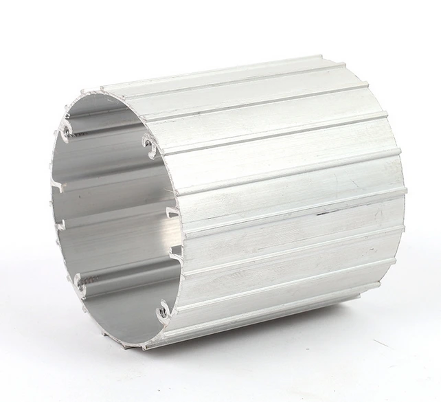
Extruded Aluminum Motor Enclosure Housing for Electric Motor Casing and Equipment Protection
An extruded aluminum motor enclosure is a protective housing formed from aluminum profiles to hold and shield an electric motor inside a machine or equipment assembly. Because the shell is produced by extrusion, the wall thickness and the internal ribs follow the mounting pattern of the motor, so the casing can be shaped to the space that is available while keeping the weight of the assembly low.
The enclosure is built around a hollow or semi hollow extruded section. Internal webs divide the body into compartments that can carry the motor, its terminal block and the cable entry. The open ends of the profile are closed with end plates, and mounting bosses or slots are machined where the motor feet or the mounting flange are fastened. Cooling openings and louver slots can be cut into the wall to let air move across the motor body when the application needs it.
The body is made from aluminum, which gives the housing a low density for the volume it encloses and allows heat from the motor to pass through the wall. Aluminum housings of this type are commonly supplied in mill finish, anodized or powder coated form, and the surface is normally matched to the environment where the equipment will be installed.
Typical applications include industrial machinery frames, pump and compressor sets, conveyor drives, HVAC fan units, automation equipment and portable power tools that need a compact motor cover. The same enclosure is also used as a motor housing on outdoor equipment and as a casing around a drive inside control cabinets.
Design starts from the motor frame size and the mounting interface. The extruded profile is sized so that the motor body fits with clearance for vibration, and the terminal opening is placed to keep cable routing short. Ribs are added on the outer face to stiffen the wall where the housing is long, and the ends are machined flat so the end plates seat without gaps. Because the section is extruded, housings of different lengths share the same wall and rib geometry.
Each batch is checked for section dimensions, wall thickness and straightness before the end plates and mounting holes are finished. Edges are deburred so the housing can be handled during assembly, and the inner surfaces are kept clean so that the motor can be fitted without further preparation.
Tell us the motor frame size, the mounting hole pattern and the space that is available, and the housing can be produced to suit. Drawings and samples are used to confirm the section before production begins, so that the finished enclosure matches the motor and the machine it serves.
The research and development of aluminium extruded motor housing have successfully replaced the motor housing in aluminium die-cast forming. These problems that motor housing in aluminium die casting faced that poor density of materials, easy to cause porosity, blowholes and other casting defects will be solved and successfully avoid the defects of poor surface casting roughness and lower corrosion resistance.
Our company has two departments-technical & producing department and trade department. Specializing in titanium materials and stainless steel products research and development, production and marketing services. We mainly produce and provide standards based on international standards and China's high-quality titanium and stainless steel products---- titanium sheets, titanium rods, titanium tube, titanium wire, titanium foil, titanium standard parts and other non-standard parts titanium, stainless steel tubes, stainless steel wire and other stainless steel products. Company production factory is located in the suburbs, now has a staff of 200 people, plant area of 100000 square meters;Company sales in the export sector, zhangjiagang channel int'l co.,ltd in urban areas, the existing staff 10 to 20 people.We will continue to innovation, sincere communication with all partners, create the biggest value for customers, welcome to contact us.
A. Our company is an integrated set of industry and trade company.
Q. How to ensure the quality of your products?
A. IS09000, client requirements, product standards, strict inspection to control raw material, production process and final
products.
Q. How do you resolve the problem about your products?
A. Person of aging services: For customer complaints commissioner set up a special complaint handling, complaint issues recorded
the first time and find the relevant person in charge of the feedback and resolve. Details check our "Quality
corrective action report".
Q. What is the MOQ?
A. It depends, different products will be different Sample order is acceptable, and some samples can be free.
Q. How long do you need the delivery time?
1)Supply within 5 -10 days (If products are in our stock list).
2)Customized products need to be calculated according to the quantity.
Q.What 's your payment terms?
A. T/T, L/C at sight , Western Union.
Q.How can we get your price ?
A. We need below information to quote for you:
1. Product Name
2. Standard
3. Material Grade (Chemical Composition)
4. Dimension
5. Quantity
6. The Drawing for Special Parts